
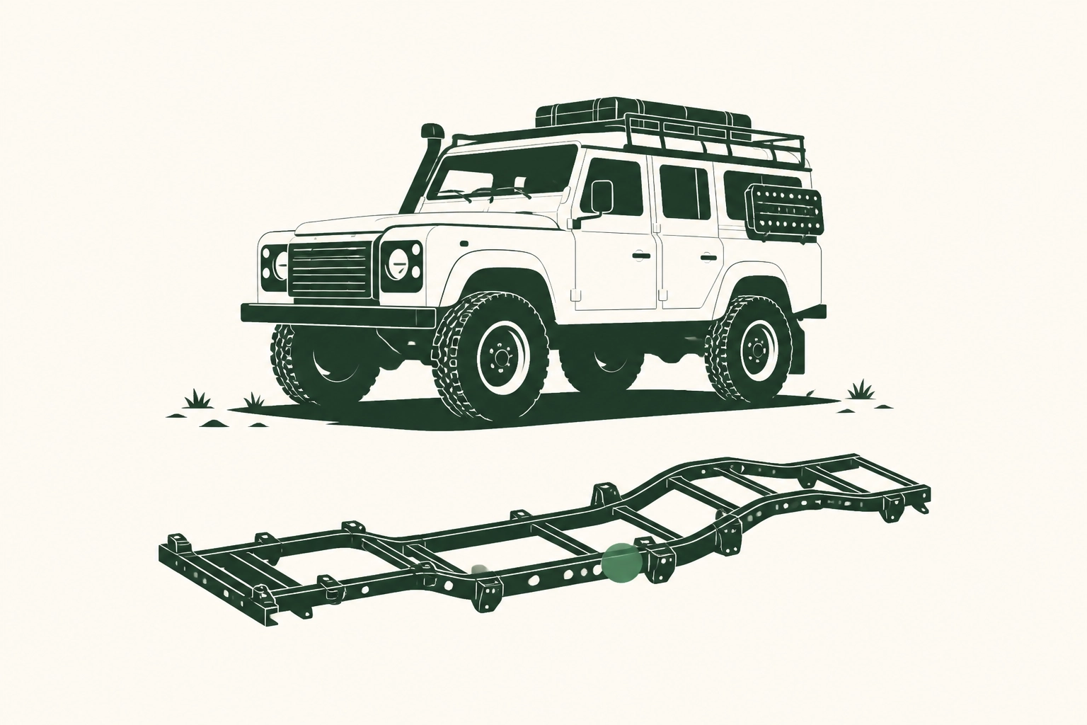
Defender 110 Overland Build: How Chassis-Stage Decisions Define Expedition Capability
Most overland vehicles fail in the field not because of what was added, but because of what was never properly considered. The difference between a Defender 110 that completes a two-week backcountry expedition and one that breaks down fifty miles from pavement is almost entirely determined by decisions made before the chassis leaves the workshop. This is not a question of budget or ambition. It is a question of methodology.
Serious expedition capability cannot be retrofitted. It must be engineered in, layer by layer, from chassis assessment through powertrain selection, suspension specification, auxiliary power architecture, and communication integration. Each decision compounds the next, and errors made early in the build sequence cannot be corrected by bolting on better equipment later.
This analysis walks through every critical specification stage of the Defender 110 overland build, from foundational chassis integrity to load management engineering and finished vehicle evaluation criteria. Whether you are briefing a builder, assessing a completed vehicle, or simply trying to understand what separates a genuinely expedition-ready build from an expensive cosmetic exercise, what follows gives you the framework to make that distinction with precision.
Expedition-Ready vs. Expedition-Adjacent: Why the Distinction Starts at the Chassis
The overland vehicle market has developed a meaningful and consequential split. On one side: Defender 110s specified as integrated systems from the day the chassis was first assessed, with every downstream decision informed by what came before it. On the other: trucks that have accumulated accessories over months or years, each addition solving an immediate problem without reference to the architecture beneath it. In photographs, these vehicles are often indistinguishable. On trail, fifty miles from pavement, they are not.
The practical consequences of that deferred methodology are financial as well as operational. A ground-up Defender 110 overland build runs $250,000 to $350,000 and requires six to twelve months of build time when executed correctly. Remediation after a build is complete costs more in both dimensions: structural corrections require dismantling finished work, electrical rearchitecting means accessing looms buried behind completed interiors, and suspension respecification on a loaded vehicle is never as accurate as suspension specified with the full load profile known from the start. Getting it right at build stage is not the expensive option.
The goal of this piece is to provide a framework that is useful before a build begins and equally useful when evaluating a finished vehicle. Not a checklist, but an analytical structure: which decisions are irreversible at each build stage, how they compound across systems, and what their presence or absence signals about the overall methodology. The kind of analysis that supports reliability built without compromise rather than simply asserting it. If you are briefing a builder or assessing a finished Defender 110, the sections that follow are the criteria worth applying.
Chassis Integrity: The Decision You Cannot Correct Later
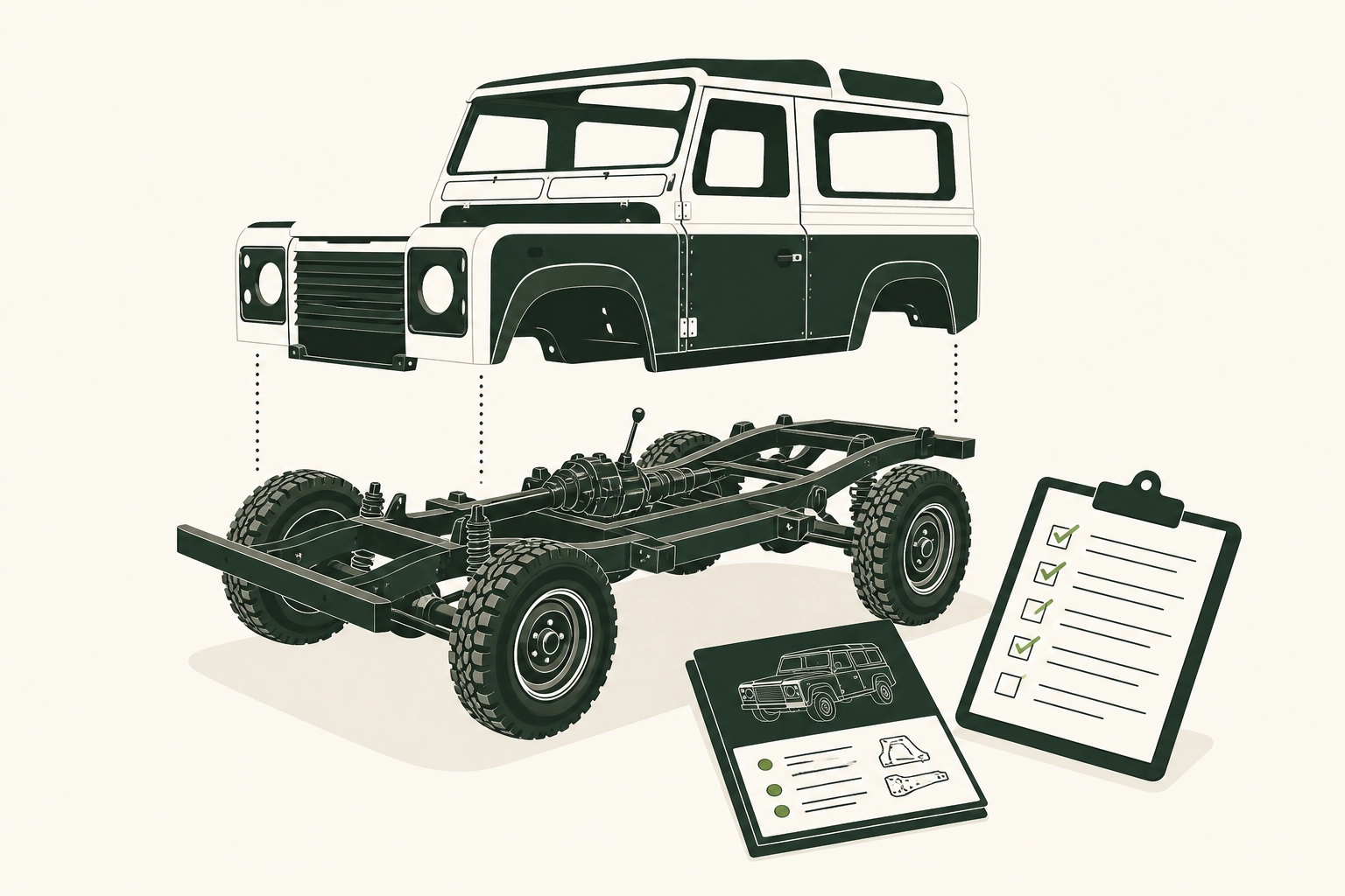
Structural assessment is not the first step of a Defender 110 overland build. It is the prerequisite that determines whether any other step is valid.
Before a builder can specify suspension rates, quote powertrain options, or plan electrical architecture, three structural conditions must be established: the bulkhead is sound, the B-posts are intact, and the rear cross-member is serviceable. Each of these governs what is physically possible downstream. A builder who skips this stage and proceeds directly to specification is not saving time; they are deferring a reckoning to the worst possible moment.
Bulkhead corrosion is the most common hidden failure point in classic Defender 110s, and it is genuinely hidden. Surface-treated or primered bulkheads can conceal advanced corrosion at the flanges, lower corners, and heater box apertures. A compromised bulkhead cannot carry the structural loads that a fully-laden expedition vehicle places on the forward chassis; every load calculation made afterward rests on a false baseline. Replacement or documented repair of the bulkhead is not a restoration nicety. It is a structural prerequisite.
B-post integrity governs more than door alignment. The B-post carries rollover protection loads and provides the primary mounting geometry for any internal roll structure or half-cage. These systems must be fitted before interior trim and lining are installed; adding them afterward requires dismantling completed work and often produces compromised mounting geometry regardless. A B-post with hidden corrosion at the base cannot anchor those structures correctly, and no amount of careful cage fabrication compensates for a compromised anchor point.
Rear cross-member condition directly affects suspension geometry specification. A corroded cross-member alters the effective spring perch position, which invalidates the load calculations a competent builder uses to select spring rates and damper travel. Replacing it before suspension work begins is not overcaution; it is the only way to ensure the geometry specification is based on accurate measurements.
For US-market builds, chassis selection carries an additional dimension. Only 534 North American Spec Defender 110s were imported to the US in 1993, all in Alpine White. That scarcity makes structural provenance documentation a meaningful part of any NAS-based build specification, not simply a historical footnote. The donor chassis is not interchangeable, and its history matters.
The clearest signal of a builder’s methodology is simple: ask for documented chassis assessment findings before any powertrain or suspension quote is produced. If those findings do not exist, the build did not begin at the right stage.
Suspension Specification: Which Decisions Compound Into Genuine Off-Road Performance
With the chassis assessed and structural integrity confirmed, suspension specification is where the 110’s inherent platform advantages either translate into genuine expedition performance or quietly disappear.
The 110’s longer wheelbase delivers real physical benefits: better weight distribution across the axle spread and improved absorption of successive impacts on broken terrain. None of that is automatic. Those advantages only materialize when the suspension is specified to exploit them under the conditions the vehicle will actually face.
Spring rate is the first compounding decision. A suspension tuned to the vehicle’s unloaded kerb weight will behave reasonably on an empty road test and deflect unpredictably under two weeks of expedition load. Fuel, water, recovery equipment, camp gear, and provisions can add substantial weight to a 110 configured for extended backcountry use. Springs selected without that payload calculation built in will run closer to full compression in the field than on the ramp, with proportionally less travel remaining for trail absorption. The result is a vehicle that drives well for the buyer and fails the expedition.
Dampers must be matched to the spring rate chosen for laden use, not selected from a generic lift kit pairing. A stiff spring with an underdamped shock produces excessive body roll on fast corrugated sections. An underdamped spring with an overdamped shock produces premature bottoming in loaded trail conditions. Both combinations accumulate mechanical stress and driver fatigue over multi-day use in ways that a single-day shakedown will not reveal.
Lift height carries consequences that extend into the drivetrain. Beyond a modest increment, increased lift alters CV joint operating angles, changes prop shaft geometry, and modifies steering feedback in ways that require compensating modifications: corrected-angle upper arms, extended brake lines, potentially a steering damper recalibration. Specifying lift without accounting for these downstream effects creates premature wear in components that are difficult to access and expensive to replace in the field.
Bump stop geometry is the most consistently overlooked element at specification stage. Once bodywork is complete and interior fitout is underway, correcting bump stop positioning becomes a significant intervention. Incorrectly positioned bump stops allow chassis contact events under full compression, and those events propagate structural fatigue through the frame over time.
Tire selection closes the loop. Steel wheels remain the correct choice for trail use; a damaged alloy is effectively write-off material in the field, while a bent steel rim can often be repaired with basic tools. Tire size should be determined by the load rating required under full expedition payload, cross-referenced against the spring rates specified, not selected to fill the arch. Defining the Specification requires treating these decisions as a single integrated system, because that is precisely what they are.
Powertrain Selection and the Serviceability Calculus for Remote Expeditions
Suspension calibration determines how the vehicle handles the terrain. Powertrain selection determines whether it can handle the consequences of being in it.
The 300TDi produces 111 horsepower in stock form. At sea level, on moderate trails, with appropriate gearing, that figure is workable. Under full expedition payload at altitude or in sustained low-range work, the margins compress quickly. The engine is not a liability; it is simply honest about its limits, and those limits have to be factored into route planning and load discipline.
The TD5 improves on torque delivery and introduces more sophisticated engine management, but that sophistication carries a cost in remote environments. In remote environments, sophisticated engine management introduces dependency on diagnostic capability that may be unavailable far from infrastructure — a trade-off worth weighing against the TD5’s torque advantages.
Modern engine swaps address the power deficit decisively. The LS3 V8 produces approximately 430 horsepower — roughly four times the stock 300TDi output. The performance argument is straightforward. The serviceability argument is more interesting: the broader North American availability of LS-series components and servicing knowledge contrasts with the specialist-tool dependency of the TD5 in remote settings. For a vehicle built for the road less travelled, that accessibility is a practical specification advantage.
The gearbox question runs parallel to the engine question but reflects a different philosophy. Manual transmissions fail in field-repairable ways; automatics frequently do not. In technical low-speed terrain, a manual gives the driver direct control over momentum management that no automatic torque converter fully replicates. The preference for manual gearboxes in serious expedition builds is not nostalgia. It is a considered position on failure modes and driver authority in situations where neither can be delegated to electronics.
Taken together, the powertrain decision defines the vehicle’s self-sufficiency envelope. Performance figures matter less than the question: what happens when something goes wrong, and how far from help does the answer leave you?
That calculus extends to recovery equipment. A high-capacity winch draws significant current under load. Specified at build stage, the charging system, cable gauge, isolators, and alternator output can be sized to sustain that draw without compromising starter battery reserve. Retrofitted afterward, the winch typically outperforms the electrical system it is bolted to. The brush guard follows similar logic: its weight and mounting geometry affect front axle load, steering feedback, and approach angle, all of which interact with suspension specification decisions already locked in. These are not accessories. They are powertrain-adjacent systems, and they belong in the same conversation.
Auxiliary Power Architecture: How Electrical Decisions Determine Expedition Autonomy
Where the charging system ends, expedition autonomy begins — and how the vehicle’s power architecture is designed to bridge that gap defines the operational ceiling.
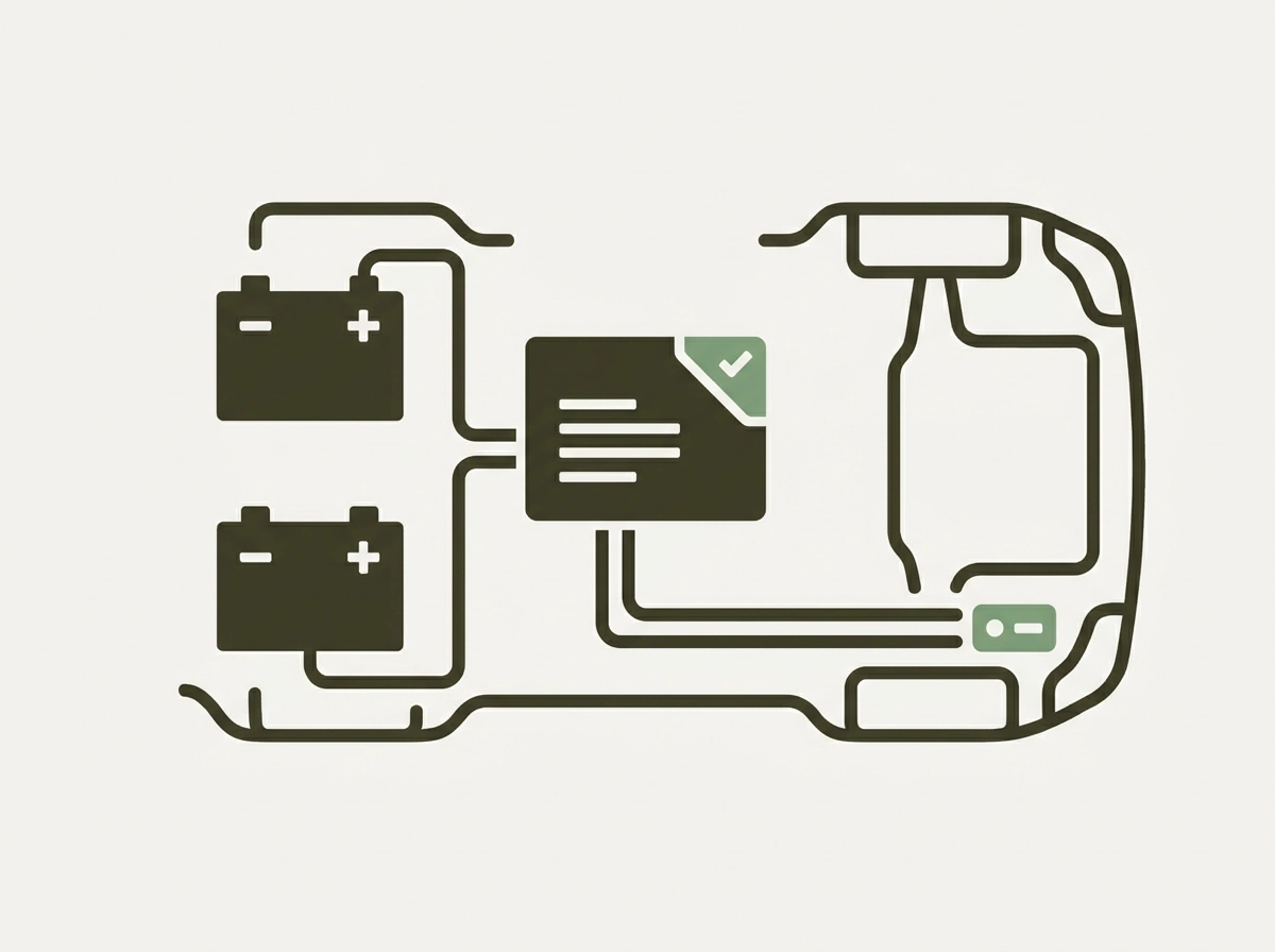
A dual-battery setup is standard specification on any serious overland build, but the presence of two batteries tells you almost nothing. What matters is the architecture connecting them: isolator type, charging topology, cable gauge, and fuse protection. A poorly specified system with quality components in the wrong configuration will delay failure, not prevent it. That distinction separates a genuine expedition asset from an expensive approximation.
Isolator selection is the most consequential single decision in the system. A voltage-sensitive relay opens the auxiliary circuit when the alternator is charging and closes it when charge drops below threshold. A simple diode isolator is cheaper and simpler, but introduces voltage drop that limits charge rate to the auxiliary bank. Neither is universally correct; the specification must match the intended use. What is always incorrect is an isolator that allows the starter battery to be drawn down during extended camp periods. In cold environments, particularly at altitude in the Rockies or high desert overnight, a compromised starter battery fails at exactly the moment reliable starting matters most.
Charging architecture must be designed for the full simultaneous load profile, not the average. Winch draw, auxiliary lighting, communication equipment, a compressor refrigerator, and navigation systems running concurrently represent a load that most retrofit wiring is not sized to sustain without voltage sag across the loom. The calculation is straightforward; the execution requires correct cable gauge from alternator to battery, battery to distribution, and distribution to consumers, with fuse protection at each stage.
Dedicated, fused circuits for each significant consumer are a build-stage requirement. Retrofitting them requires accessing bulkhead penetrations, factory loom junctions, and switch panels that are physically inaccessible once the interior is complete. A single auxiliary bus with multiple branch connections is the signature of a retrofit, not an integrated build, and it behaves accordingly under sustained load.
Solar integration follows the same logic. Roof rack structural provision, cable routing through sealed and grommeted penetrations, and charge controller placement in a ventilated space are all decisions made before the roof lining goes in. Specified afterward, each requires bodywork intervention that costs significantly more than doing it correctly at build stage.
The practical test is simple: a system that cannot sustain full expedition loads for 72 hours without the engine running is a comfort upgrade. An expedition system is defined by autonomous operation, not engine-dependent top-up. Evaluate any finished build against that criterion before accepting the electrical specification as adequate.
Communication Systems: Why Mission-Critical Equipment Requires Mission-Stage Integration
The same integration discipline that governs auxiliary power applies here, with higher stakes. Electrical failures strand you; communication failures strand you without anyone knowing.
Satellite messengers and VHF/UHF radios are consistently treated as the final items checked off before departure: clipped into a RAM mount, plugged into a 12V socket, and declared ready. That approach produces installations that work in parking lots and fail in the field. Sustained vibration, thermal cycling between desert days and high-elevation nights, and the cumulative mechanical stress of corrugated two-tracks are not conditions that consumer-grade mounting hardware and accessory-socket power taps are designed to survive over two weeks of continuous use.
Antenna Geometry Is Not an Afterthought
Where an antenna is physically located determines whether it performs when needed most. A VHF antenna mounted low on the body, behind a spare wheel carrier, or at an angle dictated by available bracketry rather than signal geometry loses effective range precisely in canyon country, dense timber, and the terrain profiles typical of the American Southwest, Pacific Northwest, and Alaska. High-frequency antennas require clear sky geometry and structural mounts that hold zero-degree vertical regardless of body flex. Those mounting points need to be engineered into the roof structure or rack at build stage; they cannot be meaningfully added to a finished vehicle without compromise.
Hardwiring Requires Access That No Longer Exists
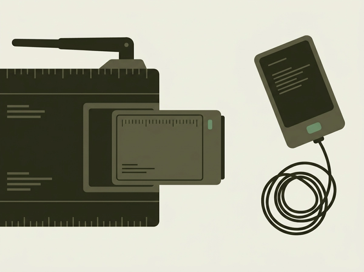
Properly integrated communication systems need dedicated power runs on protected, fused circuits, with cable routing shielded from ignition and alternator looms to prevent interference. They need physical mounting points with structural backing capable of resisting vibration-induced fatigue over thousands of miles. None of this is cleanly achievable once the dash, interior panels, and roof lining are installed. Routing a cable through a finished interior means surface runs, cable ties to existing harnesses, and grommets through trim rather than bulkhead, all of which introduce failure points that degrade over time.
Roof rack specification compounds this directly. A rack designed around load carrying often lacks the antenna mounting provisions, sealed cable exit points, and mass distribution appropriate for communication equipment added later.
The Minimum Specification for Serious US Expedition Use
For backcountry expeditions across public lands in the Southwest, Pacific Northwest, or Alaska, the functional minimum is a satellite messenger paired with redundant VHF/UHF radio capability. Both systems require integrated installation to be reliable under field conditions. Neither delivers that reliability as an improvised addition to a finished build.
Communication integration is the specification decision most commonly deferred and most directly implicated in preventable emergencies. “I’ll add that later” is a reasonable approach to a cargo net. It is not a reasonable approach to the equipment that determines whether a rescue is initiated or not.
Load Management Engineering: What Cargo Capacity Figures Do Not Tell You
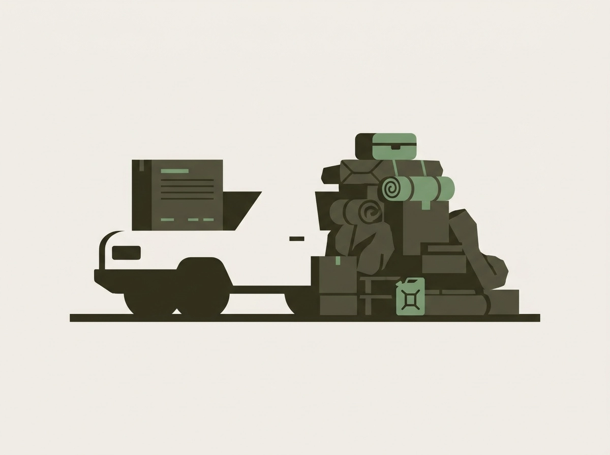
The same principle applies here: treating load management as a finishing step rather than a design parameter produces a vehicle that looks capable at a trailhead but behaves differently once it’s carrying two weeks of actual expedition weight.
The Defender 110’s 69.1 cubic feet of cargo capacity is a volume figure. It tells you how much space exists, not how that space can be loaded without compromising vehicle dynamics. A full expedition payload distributes weight in three dimensions. Volume figures say nothing about where that weight sits relative to the axles, the floor, or the roof.
Centre of gravity is an engineering variable, not an afterthought. Roof rack specification, drawer system mounting heights, and auxiliary fuel and water tank positioning all shift the vehicle’s centre of gravity in ways that suspension tuning alone cannot compensate for once the load is aboard. A high-mounted rack carrying recovery boards, a spare wheel, and a rooftop shelter raises the CoG substantially. Paired with auxiliary fuel tanks mounted high on the bulkhead rather than low in the load floor, the combined effect on cornering stability and articulation behaviour is significant. These are placement decisions made at build stage; they cannot be corrected by adjusting damper settings afterward.
Legal weight ceilings establish compliance, not capability: what matters for off-road use is whether load is distributed across axles in a way that preserves articulation and geometry.
Drawer systems and internal storage frameworks require structural mounting points in the load floor and cargo bay walls. Through-bolted anchor provisions are significantly more straightforward to engineer correctly into bare metalwork than to retrofit through a finished interior. A storage system sitting on carpet, secured by friction or compression fittings, is not load management; it is load placement.
Axle weight distribution shapes terrain behaviour. The rear axle’s relationship to total payload directly affects departure angle; front axle loading affects approach angle and steering precision in technical ground. Neither is recoverable through suspension adjustment after the load is in.
Roof rack load rating interacts with laden suspension geometry in ways that remain among the most consistently underspecified elements in expedition-adjacent builds. The combined mass of a structural rack, roof-mounted equipment, and a fully laden interior compresses suspension travel and raises roll moment simultaneously. At highway speeds on corrugated or broken surfaces, that combination degrades stability in proportion to how poorly the rack was rated and positioned relative to the vehicle’s laden geometry.
How to Evaluate a Finished Defender 110 Overland Build Against Real Criteria
All of the engineering decisions described above reveal themselves, or fail to, in the finished vehicle. Evaluating a completed build requires moving past the visual presentation and asking questions that a retrofit approach cannot answer cleanly.
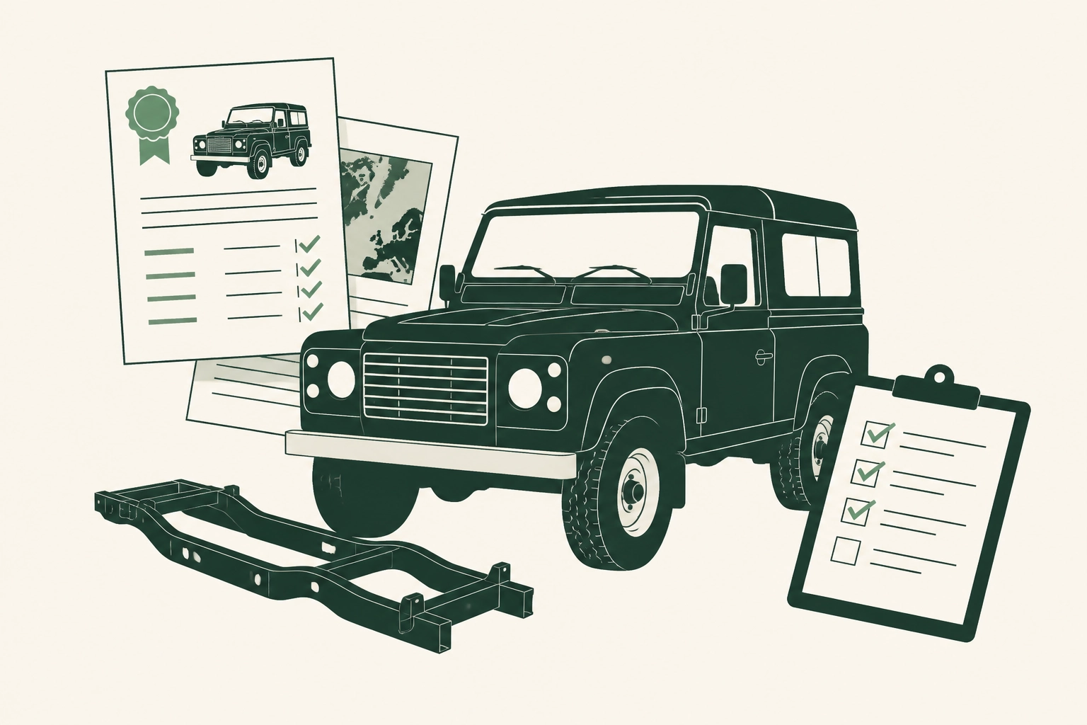
Start with the chassis record. Request documented assessment findings from before the build commenced, covering bulkhead condition, B-post integrity, and rear cross-member serviceability. The absence of pre-build records is itself a finding.
Inspect the electrical installation directly. Open the auxiliary power panel and look for labelled, individually fused, dedicated circuits. A single auxiliary bus with multiple T-taps indicates a retrofit approach: circuits added progressively rather than architected as a system. Integrated builds show wire runs that follow logical, protected paths with consistent gauge selection matched to load. Retrofit builds show the history of each addition in the wiring.
Request the suspension specification sheet. This should include spring rates, damper part numbers, and lift height. Cross-reference the tire size and load index against the spring rates specified for laden expedition use, not unladen kerb weight. A mismatch here is common in expedition-adjacent builds and produces the unpredictable deflection behaviour under load described in earlier sections.
Examine communication system cable routing. Antenna cables should pass through sealed, grommeted penetrations with protected runs physically separated from ignition and alternator looms. Surface routing with cable ties to existing harnesses indicates the system was installed after interior completion, which means neither the routing nor the interference isolation was optimised.
Assess how storage systems are mounted. Through-bolted anchor points tied to the chassis or structural load floor indicate a build that planned for loaded expedition use. The quality of that mounting detail reveals build philosophy more reliably than almost any other inspection point.
Understand what the premium reflects. Classic Defender 110s now average around $68,000 at sale. Expedition-equipped examples with documented build methodology are priced at a premium that reflects — or should reflect — verifiable decisions across chassis, electrical, suspension, and load management systems. When the documentation does not exist, the premium reflects appearance rather than substance.
Pods Overland sources, restores, and prepares Defender 110s with documented provenance and build methodology at each stage, providing the criteria-based transparency that separates a genuine expedition vehicle from an expensive approximation of one.
Specifying with Intention: The Build Brief That Changes the Journey
The evaluation criteria covered above are only useful if the framework behind them is understood, not just applied. Knowing what to inspect matters less than understanding why each element exists and how it connects to everything adjacent to it.
That cascade of interdependencies — from chassis to electrical to communication systems — is the knowledge that distinguishes a well-briefed buyer. They are not asking what components are fitted; they are asking in what sequence decisions were made and why. That distinction separates buyers who end up with vehicles that perform from buyers who end up with vehicles that impress.
Expedition-ready Defender 110s cost more than expedition-adjacent ones for a reason that rarely appears in build listings. The premium is not in the hardware. It is in the sequencing, the assessments, and the decisions made before any fabrication began. Components can be priced. Methodology cannot be retrofitted.
At Pods Overland, every Defender 110 prepared for expedition use begins with provenance verification and documented chassis assessment before systems specification opens. The build conversation starts where it must: at the foundation. What follows from that point is not a collection of overland equipment; it is a vehicle built to go further and return reliably, because that outcome was the brief from the beginning.
Conclusion
Building a genuine expedition Defender 110 is not a component selection exercise; it is a sequential engineering discipline where every decision either compounds capability or compounds compromise. Chassis integrity comes first. Suspension, powertrain, electrical architecture, and communication systems follow in an order that cannot be reversed without consequence. The difference between expedition-ready and expedition-adjacent is built into methodology, not hardware.
If you are specifying a Defender 110 for serious overland use, start by asking harder questions: about provenance, about assessment documentation, about the sequence in which decisions were made. Those questions reveal whether a build was engineered to perform or assembled to impress.
Speak with the Pods Overland team about your expedition brief. The conversation begins at the foundation, and that is precisely what makes the difference when the terrain gets serious and reliability is no longer optional.

Leave a Reply